Whether it’s a pharmaceutical plant, commercial building, hospital, airport, data center, or industrial facility, cooling is one of the largest consumers of electrical energy. Selecting the right chiller system has a direct impact on operating costs, equipment reliability, and occupant comfort.
A water-cooled chiller system is one of the most energy-efficient cooling solutions for medium- and large-capacity applications. Instead of rejecting heat directly to the surrounding air like an air-cooled chiller, it uses a condenser water loop and cooling tower to remove heat. Operating with lower condensing temperatures enables water-cooled chillers to achieve higher efficiency, particularly under continuous or high-load conditions.
This article explains the working principle, major components, operating temperatures, key performance parameters, and practical maintenance considerations of a water-cooled chiller system.
Quick Reference Legend
Abbreviation
Description
CHWS
Chilled Water Supply – Cold water leaving the chiller to cool the building or process
CHWR
Chilled Water Return – Warm water returning from the cooling load to the chiller
CWS
Condenser Water Supply – Cooled water returning from the cooling tower to the chiller condenser
CWR
Condenser Water Return – Warm water leaving the chiller condenser and flowing to the cooling tower
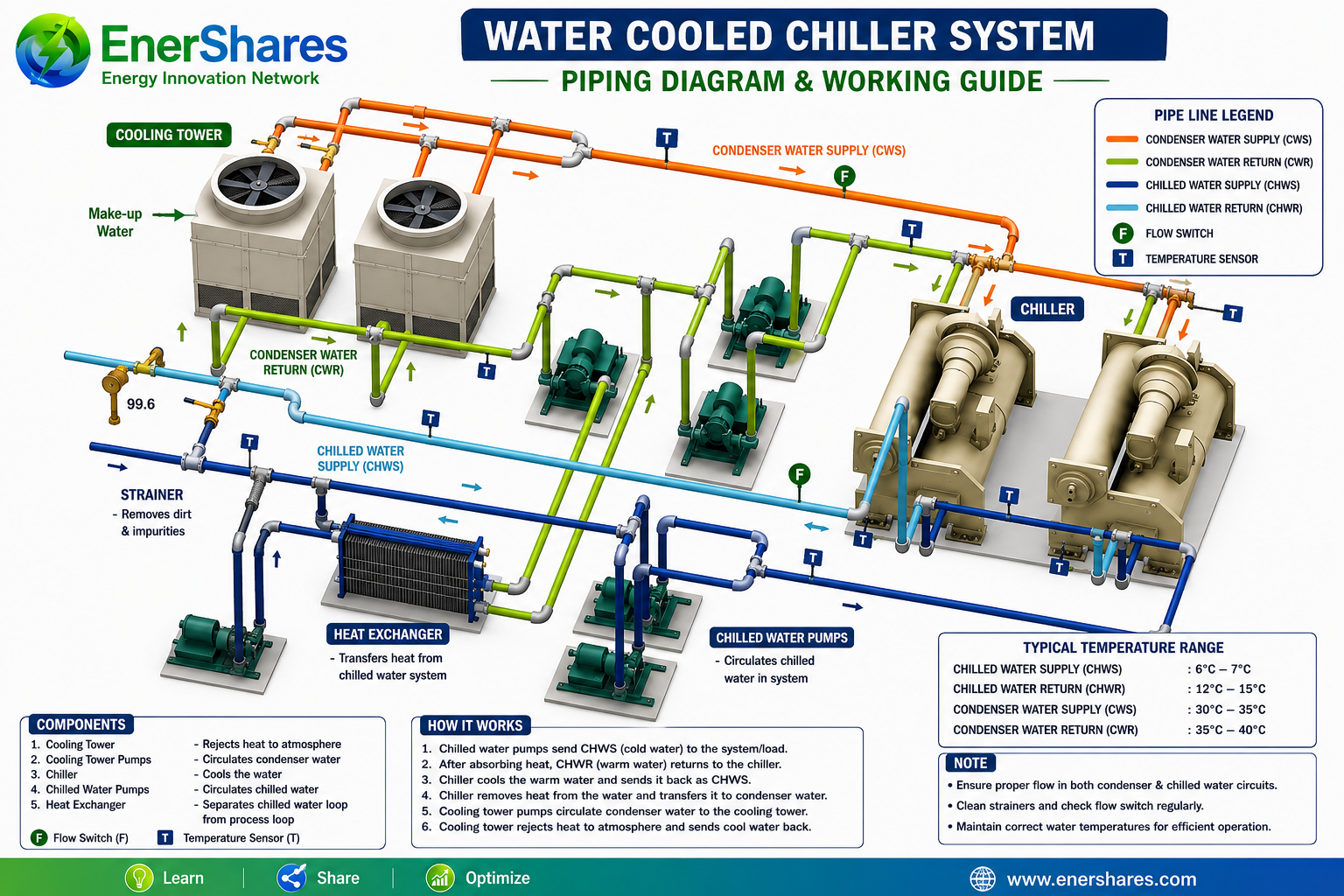
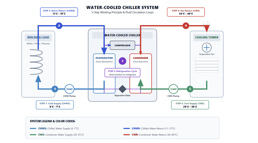
Figure 1: Complete Water-Cooled Chiller System Piping Diagram showing CHWS, CHWR, CWS, and CWR loops.
What is a Water-Cooled Chiller System?
A water-cooled chiller system is a centralized cooling setup that removes heat from a building or industrial process by circulating chilled water through cooling coils or process equipment.
The absorbed heat is transferred to the refrigerant inside the chiller. The refrigerant then transfers this heat to the condenser water, which carries it to the cooling tower. Finally, the cooling tower rejects the heat to the atmosphere through evaporative cooling.
Unlike air-cooled chillers, which reject heat directly to ambient air, water-cooled chillers use two separate water circuits to achieve higher heat transfer efficiency:
Chilled Water Circuit (Closed Loop): Delivers cooling to the building or process.
Condenser Water Circuit (Open/Semi-Open Loop): Removes heat from the chiller and rejects it through the cooling tower.
Major Components of a Water-Cooled Chiller System
1. Water-Cooled Chiller
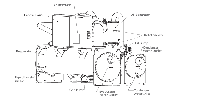
The chiller is the heart of the system. It operates on the vapor-compression refrigeration cycle and consists of four primary components:
Evaporator: Absorbs heat from the chilled water circuit.
Compressor: Increases refrigerant pressure and temperature.
Condenser: Transfers heat from the refrigerant to the condenser water.
Expansion Valve: Reduces refrigerant pressure to restart the evaporative cycle.
Depending on capacity and application, chillers may use centrifugal, screw, scroll, or reciprocating compressors.
2. Cooling Tower
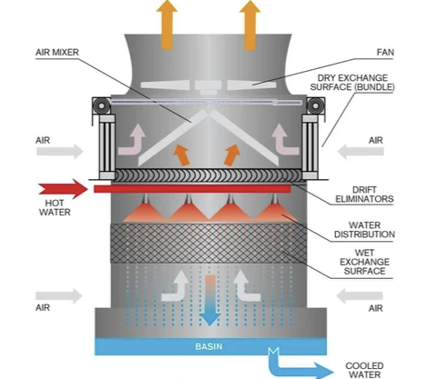
The cooling tower removes heat from the condenser water through evaporative cooling. A small portion of the circulating water evaporates, carrying away latent heat while returning cooled water to the chiller condenser. Heat is rejected primarily through evaporative cooling, where a small portion of the water evaporates and carries away latent heat.
A typical cooling tower setup includes:
Fill media
Drift eliminators
Fan and motor assembly
Makeup water line (to replace evaporative losses)
Blowdown arrangement (to control mineral buildup)
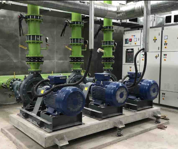
3. Chilled Water Pumps
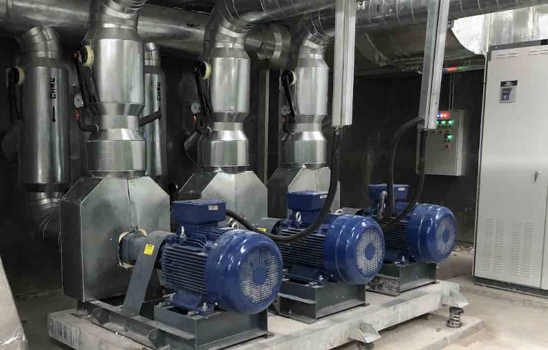
These pumps circulate chilled water between the chiller evaporator and the building’s cooling coils (AHUs, FCUs) or industrial process equipment. Maintaining the correct flow rate is essential for achieving the design cooling capacity.
4. Condenser Water Pumps
Condenser water pumps circulate water between the chiller condenser and the cooling tower, continuously transporting heat for dissipation into the atmosphere.
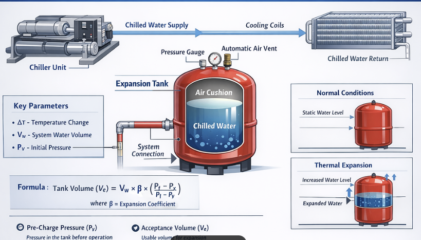
5. Expansion Tank
The expansion tank compensates for changes in water volume due to temperature fluctuations and maintains stable static pressure in the closed chilled water circuit.
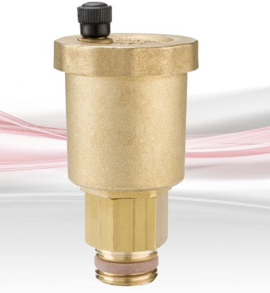
6. Air Separator and Automatic Air Vent
Entrained air reduces heat transfer efficiency and can cause corrosion, pump cavitation, and flow instability. Air separators and automatic air vents continuously remove trapped air from the piping loop.
7. Control and Safety Instruments
Reliable operation depends on proper instrumentation:
Strainers: Catch dirt and debris before water enters pumps and heat exchangers.
Flow Switches: Confirm water flow before allowing the compressor to operate (preventing freeze-ups).
Temperature Sensors (TT): Monitor supply and return temperatures across all circuits.
Pressure Gauges & Transmitters: Track pump performance and differential pressures.
Pressure Relief Valves: Protect system components from over-pressurization.
Working Principle of a Water-Cooled Chiller System
The cooling cycle operates continuously through the following 5-step sequence:
Step 1 – Cooling the Building or Process
The chilled water pumps circulate CHWS at approximately 6–7°C through AHUs, FCUs, or industrial process equipment.
As the chilled water absorbs heat, its temperature increases.
Step 2 – Warm Water Returns
The warmed water returns to the chiller as CHWR, typically between 11–15°C, depending on the system design ΔT.
Step 3 – Heat Transfer Inside the Chiller
Inside the evaporator, heat transfers from the chilled water to the refrigerant.
The refrigerant evaporates into a low-pressure vapor, is compressed to a high-pressure, high-temperature gas, and then enters the condenser, where it transfers its heat to the condenser water before condensing back into a liquid.
The expansion valve reduces the refrigerant pressure, completing the refrigeration cycle.
Step 4 – Condenser Water Removes Heat
The condenser water absorbs heat from the refrigerant and leaves the chiller as CWR.
Step 5 – Heat Rejection at the Cooling Tower
The condenser water flows to the cooling tower, where heat is rejected primarily through evaporation.
The cooled water returns to the chiller as CWS, and the cycle repeats.
Cooling Tower Range & Approach: Metrics evaluating evaporative cooling capacity.
Water Flow Rates & Pump ΔP: Verifies fluid dynamics across evaporator and condenser barrels.
Maintenance & Operational Best Practices
Performance degradation in central plants is rarely caused by compressor failure alone; it is usually driven by heat exchanger fouling, improper flow rates, or poor water treatment.
To maintain maximum efficiency:
Maintain Design Flow Rates: Verify flow using differential pressure transmitters across the evaporator and condenser.
Clean Strainers Regularly: Clogged strainers increase pump head pressures and reduce flow rates.
Monitor Approach Temperatures: Rising approach temperatures indicate tube scaling or fouling requiring chemical cleaning or mechanical brushing.
Enforce Chemical Water Treatment: Control scaling, corrosion, biological growth, and Legionella risk in the open condenser circuit.
Manage Cycles of Concentration (COC): Use automated blowdown controls to prevent mineral buildup in cooling towers.
Calibrate Sensors Annually: Inaccurate temperature or pressure readings lead to incorrect control responses from the Building Management System (BMS).
Inspect Cooling Towers: Regularly inspect fill media, drift eliminators, fan belts, gearboxes, and basin cleanliness.
Advantages & Limitations
Advantages
Superior Efficiency: Water has a higher heat capacity than air, reducing overall compressor work (kW/TR).
Long Equipment Life: Typically lasts 20–25 years when maintained properly.
Perform Under High Loads: Ideal for large installations and hot climates where ambient air temperatures impair air-cooled performance.
Higher Capital Cost: Requires cooling towers, dual pump sets, and complex piping systems.
Water Consumption: Evaporation requires continuous make-up water supply.
Higher Maintenance: Demands continuous water treatment and mechanical maintenance.
Conclusion
Water-cooled chiller systems remain the preferred choice for high-capacity applications because they deliver unmatched efficiency, long lifecycle value, and reliable cooling performance. Achieving optimal performance requires a complete understanding of how the chilled water and condenser water circuits interact, along with consistent monitoring of key parameters like ΔT, COP, and approach temperatures.
Frequently Asked Questions (FAQs)
1. What is the difference between a water-cooled chiller and an air-cooled chiller?
A water-cooled chiller rejects heat through a water loop and cooling tower using evaporative cooling, whereas an air-cooled chiller rejects heat directly to ambient air using fans. Water-cooled systems are generally more efficient for larger applications.
2. Why is a cooling tower required in a water-cooled chiller system?
The cooling tower rejects heat absorbed by the condenser water circuit into the atmosphere through evaporative cooling, returning cool water back to the chiller condenser.
3. What is the typical chilled water supply temperature?
Most commercial HVAC systems operate with a Chilled Water Supply (CHWS) temperature between 6∘C and 7∘C (43∘F−45∘F)
4. What causes Low Delta-T Syndrome?
Low ΔT occurs when returning water temperatures are lower than design levels. Common causes include excessive water flow, oversized control valves, coil fouling, open bypass valves, or unbalanced piping loops.
5. What are the most important performance metrics to monitor?
The most critical metrics include plant efficiency (kW/TR), Chilled Water ΔT, Condenser Water ΔT, Evaporator/Condenser Approach Temperatures, and Cooling Tower Approach.
Engineering leader | ISO 50001:2018 Lead Auditor | Expert in energy performance measurement & verification (M&V) | Expertise in CAPEX/OPEX | CMMS | ALCM | Audits (USFDA, MHRA, ISO, ICH, ISPE, PIC/S, ISO-14644).
Proven track record of building high-performing teams, optimizing utilities and facility management, and implementing energy conservation strategies. Adept at aligning engineering activities with business goals to drive operational excellence and cost efficiency.