
When discussing chilled water systems, most attention goes to chillers, cooling towers, or pumps. However, one small component can significantly influence system performance, controllability, and energy consumption the control valve installed at the AHU cooling coil.
Over the years, HVAC systems have evolved from constant-flow designs to variable-flow systems. As a result, the industry has gradually shifted from 3-way valves to 2-way valves in most comfort cooling applications. Understanding the difference between these two valve arrangements is important for anyone involved in HVAC design, commissioning, troubleshooting, or energy optimization.
Understanding the Basic Difference
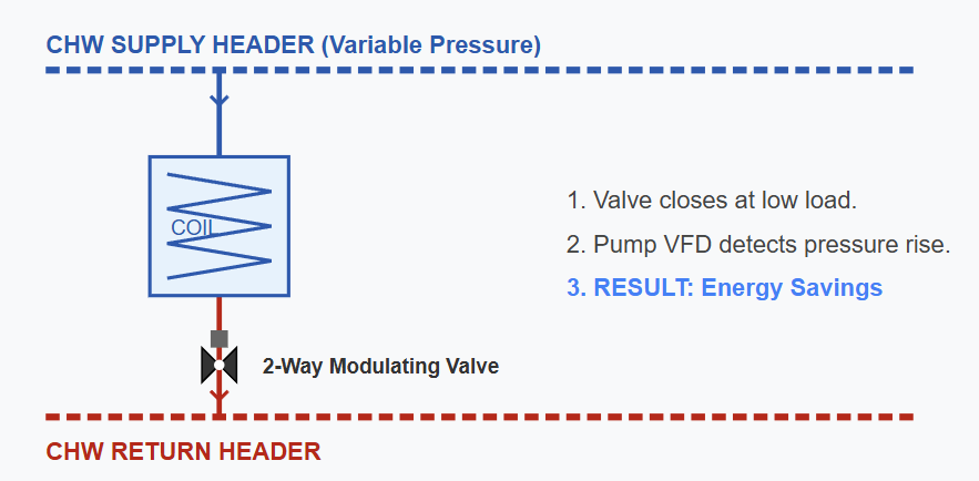
2-Way Valve
A 2-way valve is installed in series with the cooling coil and regulates the amount of chilled water flowing through it.
As room cooling demand decreases, the valve gradually closes and reduces water flow through the coil. When demand increases, it opens and allows more chilled water to pass.
In simple terms:
- Less cooling demand = Less chilled water flow
- More cooling demand = More chilled water flow
This operating philosophy forms the basis of a variable-flow chilled water system.
3-Way Valve
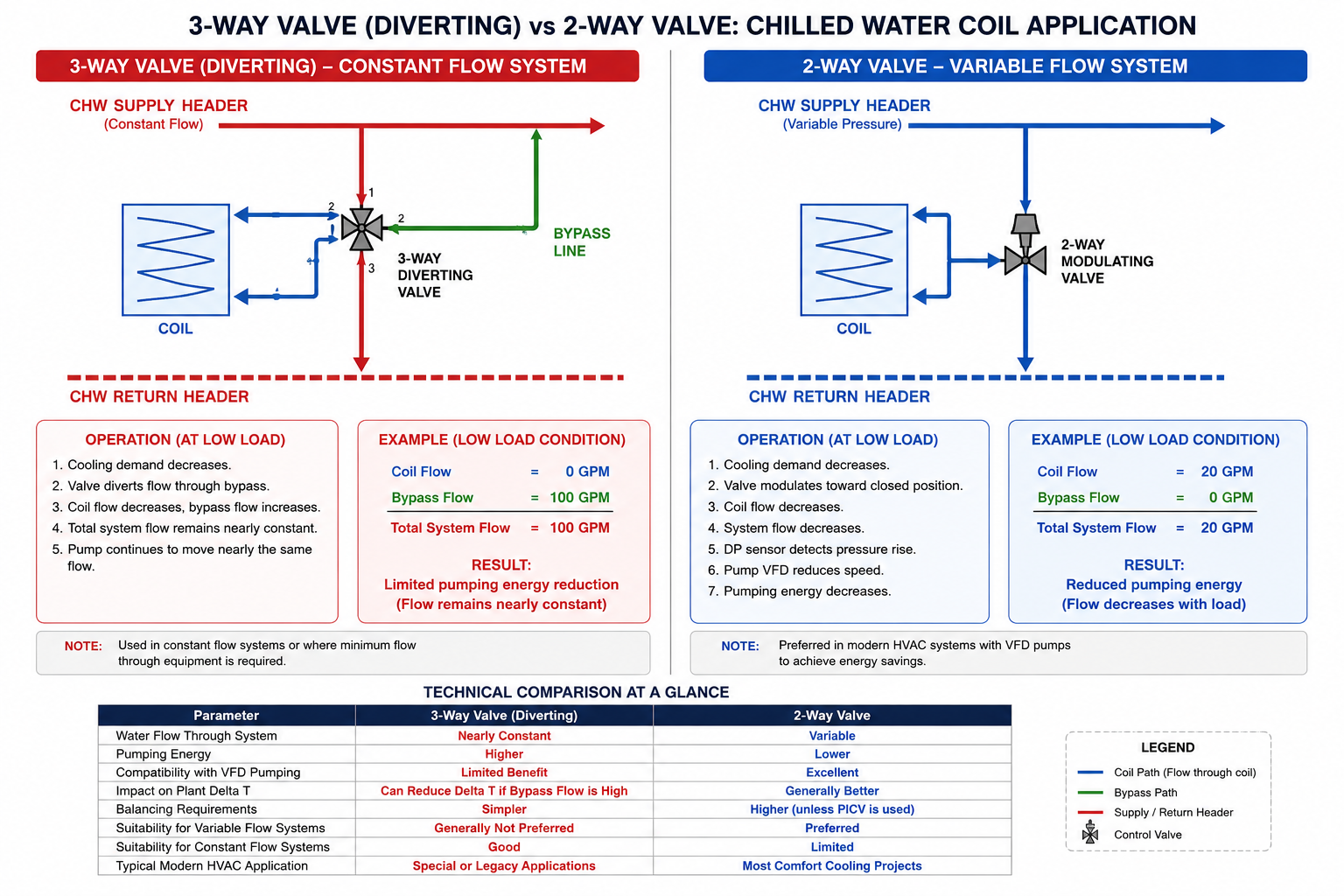
A 3-way valve works differently.
Instead of reducing total flow, it diverts water between the cooling coil and a bypass line. Even when the cooling demand is low, water continues circulating through the system.
The coil may receive less flow, but the pump continues to move nearly the same quantity of water.
This arrangement was widely used when chilled water systems operated with constant-speed pumps and chillers required a fixed flow rate.
Why 2-Way Valves Became the Industry Standard
The biggest advantage of a 2-way valve is reduced pumping energy.
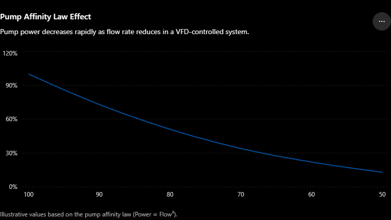
Pump affinity laws explain why. Pump power is proportional to the cube of flow rate. This means that even a small reduction in flow can produce a significant reduction in power consumption.
For example, if flow reduces by 20%, the theoretical pump power requirement reduces to approximately 51% of the original value. In other words, a 20% reduction in flow can potentially reduce pumping power by nearly 50%.
Of course, actual savings depend on system characteristics, static head, pump efficiency, and control strategy, but the energy reduction can still be substantial.
In retrofit projects, one of the most common findings is the installation of VFDs on chilled water pumps while retaining existing 3-way valves. Although the pumps are technically variable speed, the bypass flow created by the 3-way valves often prevents the system from achieving the expected energy savings.
This is one of the primary reasons why modern chilled water systems are generally designed with 2-way control valves.
Why 2-Way Valves Save Energy
- 100% Flow → 100% Pump Power
- 80% Flow → 51% Pump Power
- 50% Flow → 13% Pump Power
A 20% reduction in chilled water flow can theoretically reduce pumping power by nearly 50%.
Impact on Chilled Water Delta T
Another important consideration is chilled water Delta T.
When excessive bypassing occurs through 3-way valves, a portion of the chilled supply water returns to the plant without absorbing heat from the conditioned space. This can reduce the return water temperature and lower the overall system Delta T.
A low Delta T condition forces the plant to circulate more water to satisfy the same cooling load, increasing pumping requirements and potentially reducing overall plant efficiency.
It is important to note that 3-way valves are not the only cause of low Delta T. Coil fouling, excessive water flow, poor balancing, improper control sequences, and low-load operating conditions can produce similar symptoms.
The Often-Ignored Factor: Valve Authority
Many temperature control issues are blamed on sensors, actuators, or BMS programming when the actual problem is poor valve sizing.
Valve authority is the relationship between the pressure drop across the control valve and the pressure drop across the entire branch circuit.
As a general guideline, designers aim for a valve authority between 0.3 and 0.7.
When a valve is oversized, a small movement of the valve can create a large change in flow. The result is unstable temperature control, hunting, excessive actuator movement, and occupant complaints.
Proper valve selection is therefore just as important as selecting the correct coil or pump.
Bottom Line
If the control valve is selected purely based on pipe size, there is a good chance it has been oversized. Control valves should be selected based on the required flow rate and Cv value, not pipe diameter. Proper sizing improves valve authority, controllability, and temperature stability.
Pressure Independent Control Valves (PICVs)
Pressure fluctuations are common in variable-flow systems because control valves throughout the building continuously open and close.
A conventional 2-way valve can be affected by these pressure variations, making balancing and control more difficult.
PICVs address this challenge by incorporating an internal pressure regulator that maintains the design flow rate over a wide pressure range.
From a commissioning perspective, PICVs simplify balancing, improve control stability, and reduce many of the issues traditionally associated with variable-flow systems.
For this reason, PICVs are increasingly becoming the preferred choice in modern HVAC projects.
Designer’s Note
In variable-flow chilled water systems, minimum flow requirements must always be considered. Depending on the plant design, this may be achieved through dedicated bypass arrangements, decoupler piping, or, in some cases, selected 3-way valve applications.
The objective is to ensure stable system operation while preserving the energy-saving benefits of variable flow.
Are There Still Applications for 3-Way Valves?
Yes.
Although 2-way valves are generally preferred for energy-efficient chilled water systems, 3-way valves still have valid applications.
Typical examples include:
- Existing constant-flow chilled water systems
- Process cooling applications requiring stable flow conditions
- Certain legacy chiller installations with minimum flow limitations
- Special applications where continuous circulation through equipment is required
The decision should always be based on system requirements rather than a blanket preference for one valve type.
Common Design Mistakes
Installing VFDs but Retaining Existing 3-Way Valves
This is one of the most common retrofit issues. The pumping system remains unable to take full advantage of variable-flow operation.
Incorrect DP Sensor Location
Differential pressure sensors should generally be located near the hydraulically most remote critical branch so that all coils receive adequate flow under varying load conditions.
Valve Oversizing
Selecting a valve based solely on pipe size often leads to poor controllability. Valve selection should always be based on the required flow rate and valve Cv value.
Technical Comparison at a Glance
| Parameter | 2-Way Valve | 3-Way Valve |
|---|---|---|
| Water Flow Through System | Variable | Nearly Constant |
| Pumping Energy | Lower | Higher |
| Compatibility with VFD Pumping | Excellent | Limited Benefit |
| Impact on Plant Delta T | Generally Better | Can Reduce Delta T if Bypass Flow is High |
| Balancing Requirements | Higher (unless PICV is used) | Simpler |
| Suitability for Variable Flow Systems | Preferred | Generally Not Preferred |
| Suitability for Constant Flow Systems | Limited | Good |
| Typical Modern HVAC Application | Most Comfort Cooling Projects | Special or Legacy Applications |
Final Thoughts
For most modern comfort cooling applications, 2-way control valves have become the preferred solution because they support variable-flow operation, reduce pumping energy, and help improve overall plant efficiency.
However, valve selection alone does not guarantee good system performance. Proper hydraulic design, valve sizing, differential pressure control, balancing, and commissioning are equally important.
A well-designed 2-way valve system can significantly improve chiller plant performance, maintain design Delta T, and reduce operating costs. The real objective is not simply choosing between a 2-way or 3-way valve, it is designing a chilled water system that remains stable, efficient, and controllable throughout its operating life.
⚡ Enjoying this article? Stay updated with weekly HVAC & Energy Hacks — straight on WhatsApp!
💚 Join Our WhatsApp Channel